
Define the Electrical Function and Measurement Basis
First define why charge must be controlled. The need may be charge limitation, timed dissipation, grounding, ESD protection, dust control, or another specific function. Antistatic, static-dissipative, and conductive can have different boundaries across customer and industry specifications.
Name the measured quantity, method, units, voltage, electrode arrangement, geometry, thickness, conditioning, environment, locations, target, and production variation. Surface and volume results are not interchangeable. Do not relabel resistance as resistivity without the required geometry conversion.
- Electrical function, failure risk and required grounding path
- Surface, volume or static-decay method with exact units
- Voltage, electrodes, thickness, conditioning, temperature and humidity
- Measurement locations, sample quantity and acceptable variation
Choose PA6, PA66 or PPA From the Non-Electrical Requirements
The conductive system does not replace the base-polymer decision. Compare load, stiffness, impact, wear, temperature, moisture, chemicals, dimensions, flame or regulatory requirements, appearance and processing feasibility first. Then confirm that the required electrical technology is available in the suitable matrix.
PA6 and PA66 require clear dry and conditioned states because moisture can affect dimensions, mechanics and electrical behavior. PPA may merit review when the application has a defined elevated-temperature, humid-environment, chemical or dimensional requirement beyond the selected PA66 direction. The exact conductive formulation can change the normal matrix behavior, so unmodified polymer data is only a starting reference.
Compare CNT and Carbon-Fiber Directions
Taiyi Polymer positions the CNT series for permanent static control. The carbon-fiber series targets controlled conductivity, with a separate thermal-conductive review path. CNT and carbon fiber form different networks. Their electrical, density, stiffness, impact, flow, surface, wear, color, and cost balances can differ.
Carbon fiber can introduce mechanical reinforcement and directional electrical or dimensional behavior as fibers align with molded flow. CNT performance depends on the dispersed network and its survival through compounding and molding. Neither technology should be selected only from a generic label. Compare the exact grade, matrix, target band, mechanical data, processing guidance and finished-part evidence.
- Required electrical band and stability over humidity and temperature
- Mechanical reinforcement, impact, wear and mating-surface requirements
- Density, color, surface, cleanliness and contamination constraints
- Flow, weld lines, orientation, regrind policy and process robustness
Treat Catalogue Bands as Screening Codes
The current Taiyi conductive catalogue provides target-band labels for PA6, PA66 and PPA CNT and carbon-fiber grades. It does not state in each entry whether the label is a surface or volume quantity, its units, specimen thickness, conditioning or test method. The band can therefore be used to shortlist a grade direction but must not be published as a complete electrical specification by itself.
Before trial, obtain the grade-specific electrical basis. Agree how the catalogue band maps to the project test. Confirm whether limits apply to a standard plaque or finished part. Define the measured surfaces and flow directions, and whether the target is initial, allowed, or retained after exposure.
Taiyi PA and PPA conductive catalogue directions
Design the Part, Conductive Network and Ground Together
A material can dissipate charge only through the path created by the compound, part and assembly. Review wall thickness, ribs, gates, flow direction, weld lines, inserts, fasteners, coatings, labels, contamination, contact pressure and the location and durability of ground connections. Resin-rich surfaces or interrupted contact regions may produce a different result from a standard plaque.
Measure multiple locations and orientations where the filler network may be directional or where weld lines separate flow fronts. Include contact resistance and assembly interfaces when they are part of the discharge path. A low material resistivity value does not prove that an isolated or poorly grounded component will control charge in service.
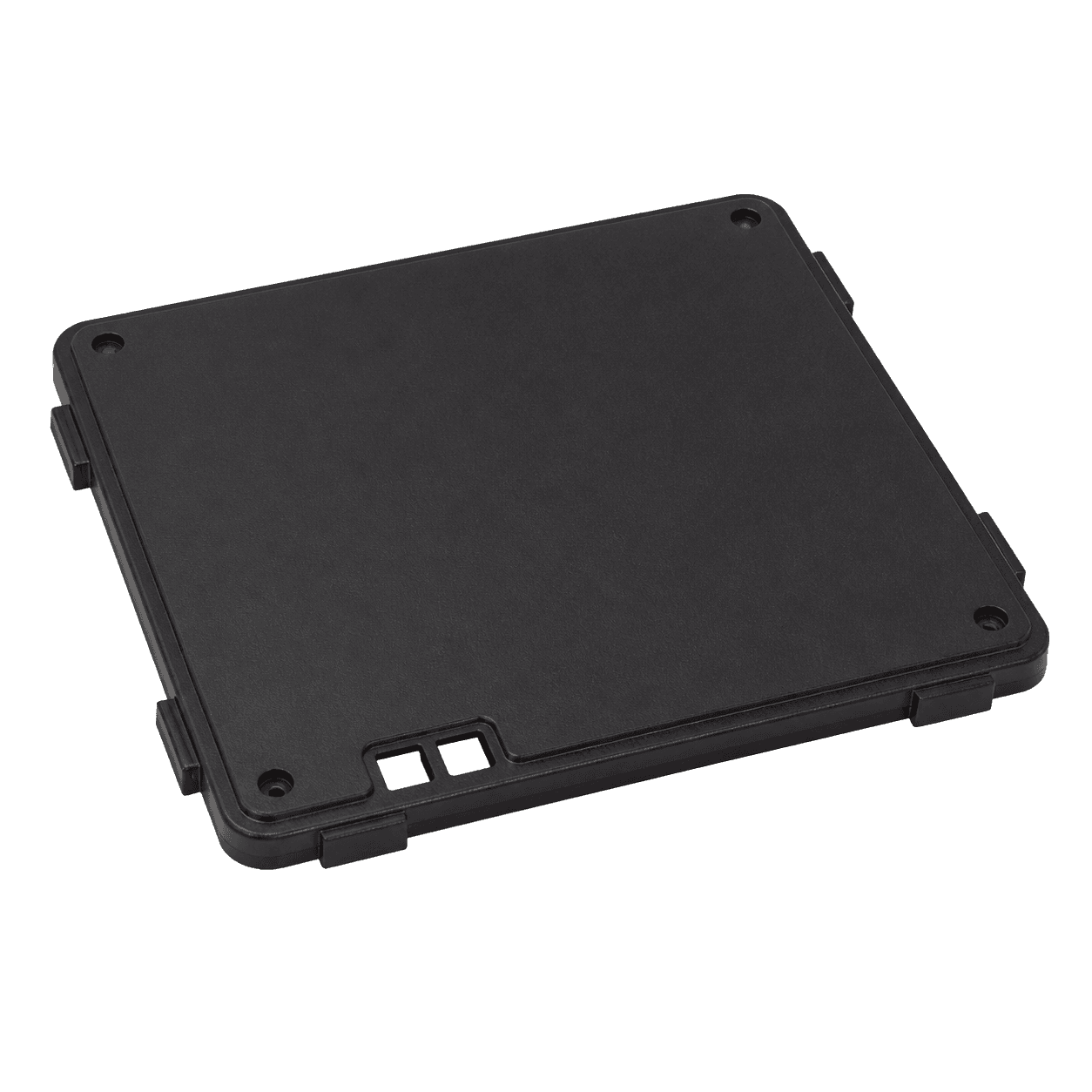
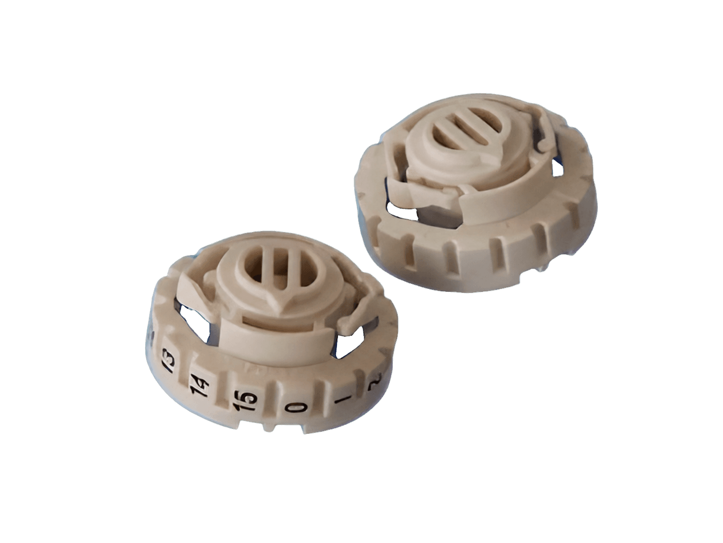
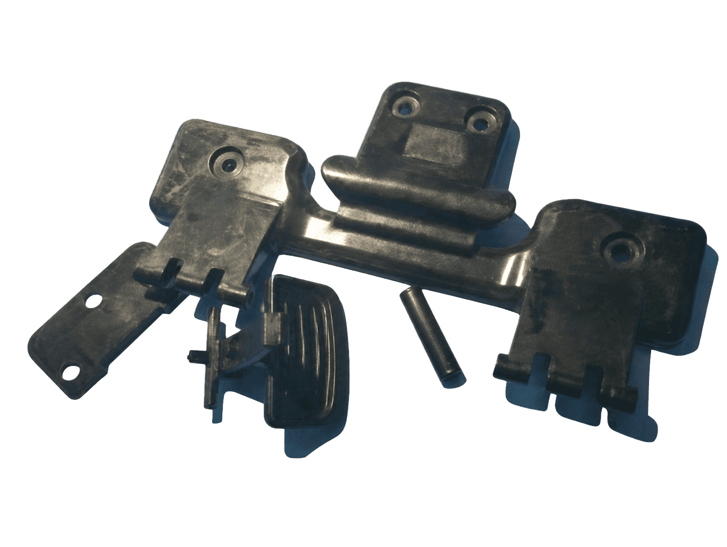
These are representative electrical-part geometries only. Verify grounding, wall thickness, flow, inserts, contacts, and test method on the actual part. The images do not imply conductivity or a grade.
- Control-box cover
- Rotary electrical part
- Control-box components
Control Molding Variables That Affect Electrical Results
Dispersion, orientation, shear, residence, gates, runners, weld lines, packing, thickness, surface formation, and regrind can affect the conductive network. Establish grade-specific handling and a stable molding window. Do not copy an unfilled PA or PPA process sheet.
For every electrical sample, record lot, moisture, regrind, machine, temperatures, fill and transfer data, pressure, cushion, part weight, cavity balance, and surface condition. Test cavity-marked parts at defined locations and conditioning. If results move with the process, investigate the molding and network interaction.
Qualify Electrical and Mechanical Performance Together
Validate the required surface, volume or decay result on the intended part and assembly under specified temperature, humidity and conditioning. Include production variation across relevant cavities, locations, flow directions, lots and process conditions based on project risk. Recheck after aging, chemical exposure, wear, cleaning or thermal cycling when these can affect the conductive path.
Complete mechanical, dimensional, impact, wear, flame, regulatory, cleanliness and appearance tests alongside the electrical work. Approve the exact grade, color, process, regrind rule, test method, grounding design and document set. Do not release a material only because one plaque measurement falls inside the catalogue band.