
Define the Performance Gap Before Choosing a Fiber
Start with the result the current material or design cannot achieve. The gap may involve deflection under load, creep, dimensional movement, weight, electrical behavior, temperature, surface quality, wear, or a combination of these factors. A request for 'more stiffness' is incomplete until the load direction, duration, temperature, allowable movement, and test method are defined.
For an existing component, compare the current material, measured failure, part drawing, molding record, and acceptance limit. For a new component, define the load cases, critical dimensions, assembly, environment, safety factors, appearance limits, and validation method before selecting the polymer matrix or fiber system.
- Load direction, duration, cycling, impact, and allowable deformation
- Critical dimensions, tolerances, creep, and thermal or moisture exposure
- Electrical, weight, surface, color, wear, and counterpart requirements
- Current baseline, failure evidence, target result, and pass criteria
Glass Fiber and Carbon Fiber Solve Different Problems
Glass fiber is commonly screened when stiffness, creep control, load retention, or dimensional response must improve within a practical engineering compound direction. Carbon fiber may merit a separate review when stiffness-to-weight balance, a carbon-fiber-specific dimensional response, or an electrical function is central to the project. Neither direction guarantees the finished-part result by material name alone.
Both fiber systems can create directional behavior because the molded fiber orientation follows the part geometry and flow history. Gate position, flow length, weld lines, ribs, bosses, wall changes, and load direction therefore influence the result. Compare the directions on molded-part behavior, processing feasibility, documentation, and total project requirements—not fiber percentage alone.
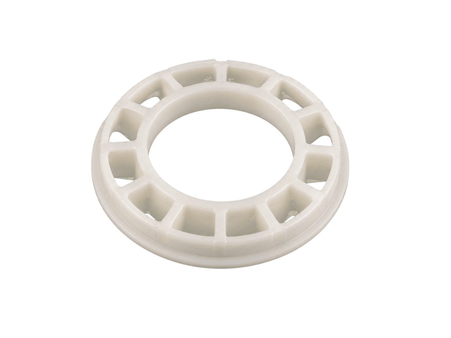
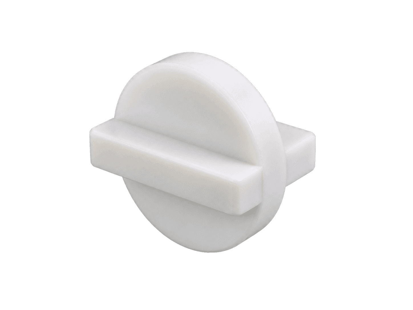
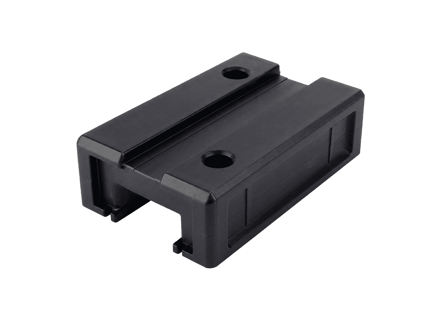
Representative application geometries only. Load direction, flow path, orientation, mating surfaces, and dimensional datums must be verified on the actual molded part; the images do not identify a final reinforcement level.
- Bearing cage geometry
- Coupling insert
- Linear guide block
Choose the Polymer Matrix Before Finalizing the Reinforcement
The reinforcement decision cannot be separated from the base polymer. POM may remain relevant where precision molding, sliding behavior, low moisture response, or the existing application platform favors POM. PA6, PA66, PPA, PPS, or another engineering polymer may require review when the temperature, chemical, structural, electrical, or processing target points to a different balance.
Use the documented POM GF10 to GF30 range as the first screening route where it fits the part. High-fill glass fiber and carbon fiber directions should be treated as project-development work for an appropriate polymer family, with the formulation, processing guidance, data package, and documentation defined for that project.
Release the Molded Part, Not the Fiber Percentage
A useful program moves through clear evidence gates. First compare available grade data and confirm the required documents. Next review mold filling, orientation, weld lines, tooling, machine capability, and expected process risk. Then mold traceable samples and measure dimensions, warpage, appearance, assembly, mechanical or electrical function, and environmental retention against the agreed baseline.
Production release should use the exact formulation, color, process window, conditioning method, test method, and acceptance criteria. Generic reinforcement values or an undeclared development capability should not be used as a substitute for grade-specific data and representative molded-part validation.