
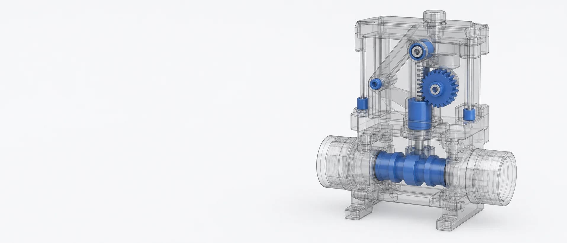
CAD visualization showing a molded valve spool, flow body, and actuation mechanism

Fluid control components

Valve spools and cartridges

Determine whether molded POM fits selected valve internals affected by sticking, leakage, scoring, dimensional drift, or unstable actuation. Pressure, medium, seals, clearance, and flow function define the application boundary first.

For selected low- or moderate-pressure spools, pistons, guides, cartridge cages, seal carriers, and flow-control inserts.

Pressure
Normal, peak, and differential
Clearance
Spool, bore, and geometry
Medium
Fluid, concentration, temperature
Seals
Material, compression, friction
Motion
Stroke, force, and cycles
Target
Leakage, flow, and life

Where this component appears

Start with the valve-function problem.

Sticking, leakage, scoring, or variable flow can originate in pressure forces, clearance, seals, contamination, fluid chemistry, tooling, or the compound. Diagnose the valve before changing polymer.

01
Observed problem

Sticking, high actuation force, or slow return

Check first

Check spool-to-bore clearance, cylindricity, concentricity, seal compression, contamination, temperature, lubrication, and pressure forces through the full stroke.

Material response

Screen low-friction or balanced POM only after geometry, seal, debris, and thermal-clearance causes are controlled.

02
Observed problem

Increasing leakage or variable flow

Check first

Inspect seals, spool and bore wear, scoring, creep, metering geometry, cavity variation, actual clearance, temperature, and spool position.

Material response

Compare dimensionally stable POM only when material wear or deformation remains part of the limiting mechanism.

03
Observed problem

Scoring, intermittent movement, or debris

Check first

Identify the particle source, filtration and cleanliness, surface finish, port edges, alignment, seal damage, and fluid contamination.

Material response

Evaluate tribological modification only after abrasive contamination and damaging geometry are separated from compound behavior.

04
Observed problem

Cracking, distortion, or loss of retention

Check first

Review pressure and surge loads, thin sections, weld lines, assembly stress, fluid compatibility, temperature, core accuracy, and gate location.

Material response

Consider reinforced POM or a higher-temperature polymer only when structural and chemical boundaries justify it.

Candidate materials

Compare candidate materials by their response to the part.

Compare the options below against pressure, fluid chemistry, clearance, seals, actuation, contamination, and leakage targets.

  1. 01

    Balanced / unfilled POM

    A baseline for selected moving pistons, guides, cartridges, and valve internals needing dimensional stability, stiffness, moldability, and sliding behavior.

  2. 02

    Wear-resistant or low-friction POM

    A candidate when repeatable testing shows friction, wear, stick-slip, or unstable actuation force is a genuine material limitation.

    Project caution

    A lower friction value cannot correct excessive seal compression, sharp port edges, contamination, or an inadequate spool-to-bore clearance.

  3. 03

    Reinforced POM

    A reinforced option for selected cartridge cages, carriers, or guides where stiffness and deformation control dominate.

    Project caution

    Fiber orientation can affect roundness, shrinkage, and seal or bore interaction, so it is not an automatic choice for precision spool lands.

  4. 04

    PA or PPA structural option

    A separate project path when a valve component needs a different hot, wet, or structural balance than the validated POM window can provide.

    Project caution

    Moisture, chemical compatibility, processing, dimensions, seals, pressure, and cost require their own validation; this is not a direct drop-in substitution.

Minimum project input

Send the project inputs already available.

A drawing and the current operating conditions are enough to begin. Remaining details can follow after the first response.

01

Component and function

  • Part drawing, 3D model, component role, and current material
  • Spool lands, ports, cartridge body, guide, seal carrier, and critical datums
02

Pressure and flow

  • Normal, peak, differential, surge, and pulsation pressure
  • Flow direction, rate, metering requirement, and acceptable leakage
03

Fluid and temperature

  • Exact medium, concentration, additives, cleaners, and exposure cycle
  • Operating, cleaning, storage, and peak temperature conditions
04

Clearance and seals

  • Mating-bore material, diameter, finish, geometry, and functional clearance
  • Seal material, groove geometry, compression, lubrication, and port-edge condition
05

Actuation and duty

  • Stroke, cycle rate, available force, spring load, and return requirement
  • Contamination level, filtration, cleanliness, and representative particle exposure
06

Target and status

  • Tooling stage, cavity count, production volume, and current failure symptom
  • Target leakage, flow accuracy, actuation force, cycle life, and documents
Expected output

A material-fit decision, candidate shortlist, available grade data or document path, and a proposed valve-level evaluation plan.

Find Grade Data & TDS

Open the detail when the project needs it.

Review material choices, molding priorities and reported project stages for similar parts.

View all customer cases

Project input

Shortlist valve material candidates.

Use the project brief above to compare material directions, available grade data, and a valve-level validation plan.