
Define the Gear Duty Before Comparing Materials
Begin with the transmission requirement rather than a preferred resin name. Record gear type, module or diametral pitch, tooth count, face width, ratio, input and output torque, speed range, rotation direction, starts and stops, duty cycle, required life, and acceptable backlash. Distinguish normal running torque from startup, stall, jam, reversal, braking, and other shock events.
Define the operating environment around the gear mesh. Ambient temperature alone may not represent the tooth temperature because speed, load, friction, and lubrication can generate local heat. Include nearby heat sources, cooling, chemicals, dust, washdown, humidity, expected noise, maintenance limits, and whether the gear must run dry, with initial lubrication, or with continuous lubrication.
- Torque spectrum, speed range, reversals, shock and expected cycles
- Gear geometry, shaft support, alignment, housing stiffness and backlash
- Ambient and local temperature, chemicals, contamination and moisture
- Lubrication method, maintenance interval, noise and efficiency target
Identify the Governing Failure Mode
Gear teeth can fail at the root from repeated bending, at the flank from wear or surface damage, or through deformation that changes the mesh. Creep, thermal expansion, molded shrinkage, bore movement, hub stress, shaft misalignment, and housing movement can alter backlash and tooth contact even when the material does not fracture.
Do not collapse these risks into one request for a 'stronger' or 'more wear-resistant' grade. A higher modulus may reduce tooth deflection but does not automatically improve impact tolerance, weld-line performance, noise, or mating-part wear. Likewise, a lower friction result does not by itself establish fatigue life or dimensional accuracy. Rank each failure mode and define how it will be measured.
Gear failure evidence map
Evaluate the Complete Contact Pair
The same POM grade can behave differently against hardened steel, softer metal, another POM, PA, or a coated surface. Record the driver and driven materials, surface hardness and finish, tooth geometry, contact pattern, alignment, lubrication, pressure, speed, and expected debris or contamination. Wear on the mating gear may be as important as wear on the POM gear.
Review breakaway and running friction, adhesive or abrasive wear, noise, vibration, frictional heat, lubricant compatibility, and run-in behavior separately. Plastic-on-plastic contact and dry running require particular care because heat dissipation and adhesive wear can govern the result. Use grade-specific tribology data only when the mating material, pressure, speed, temperature, surface and test method are relevant to the application.
- Driver and driven material, hardness, finish and tooth contact pattern
- Dry, initially lubricated or continuously lubricated operating condition
- Pressure, sliding and rolling speed, duty, temperature and heat removal
- Wear of both gears, noise, efficiency, debris and lubricant condition
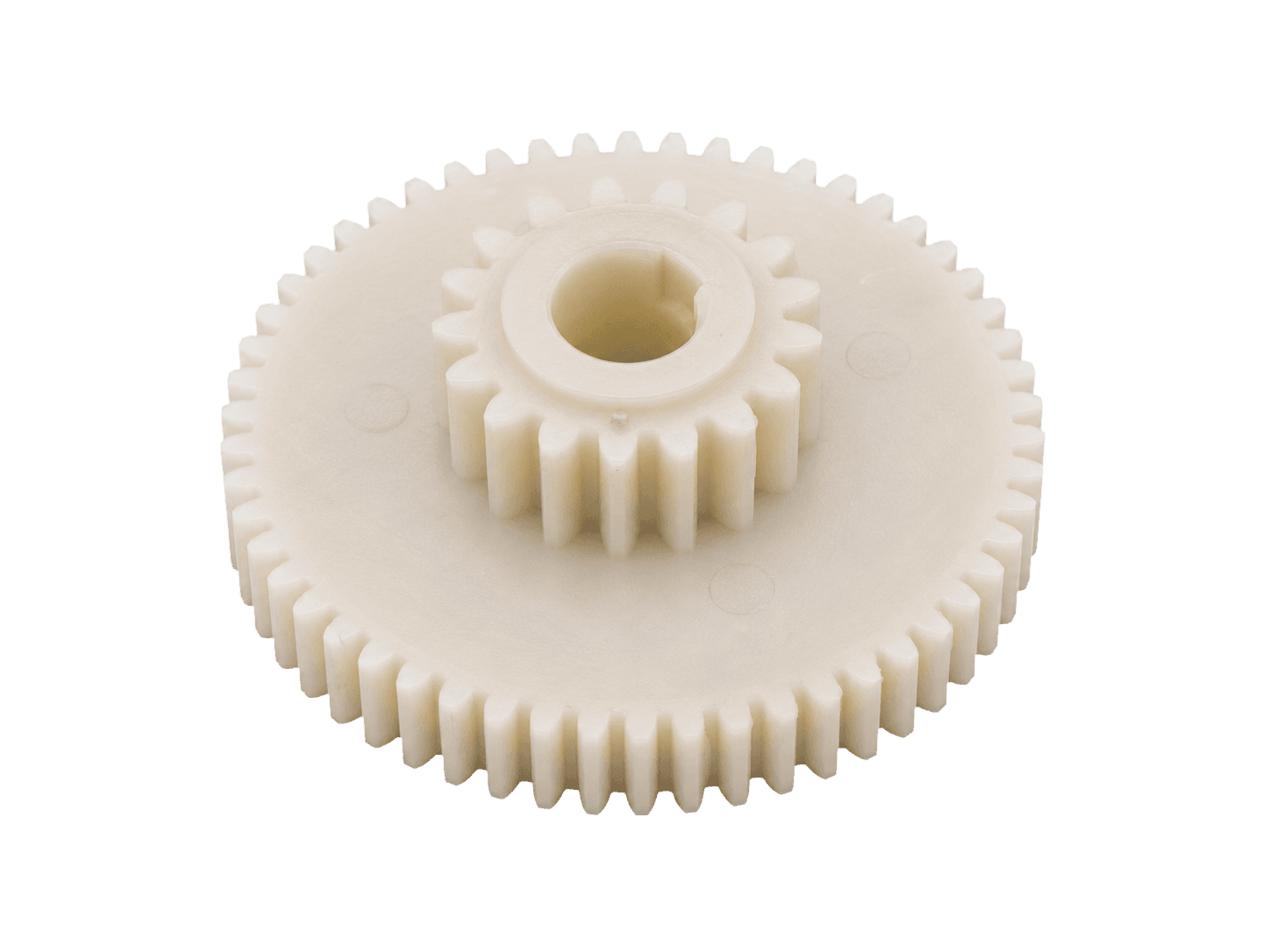
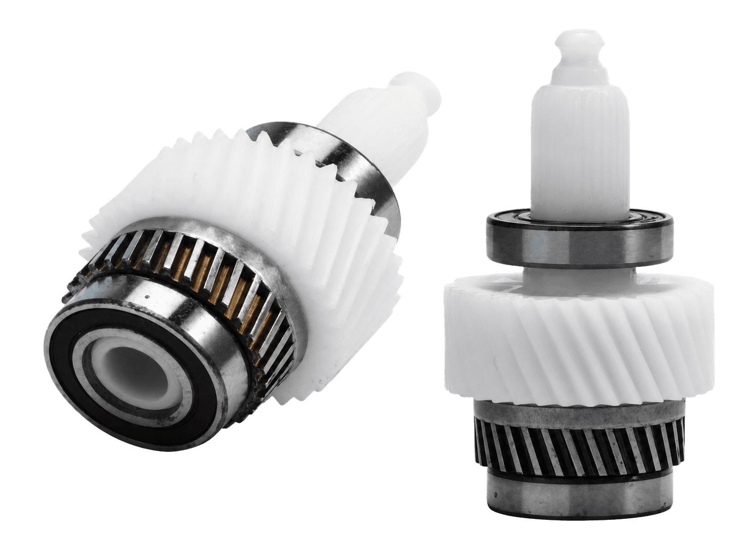
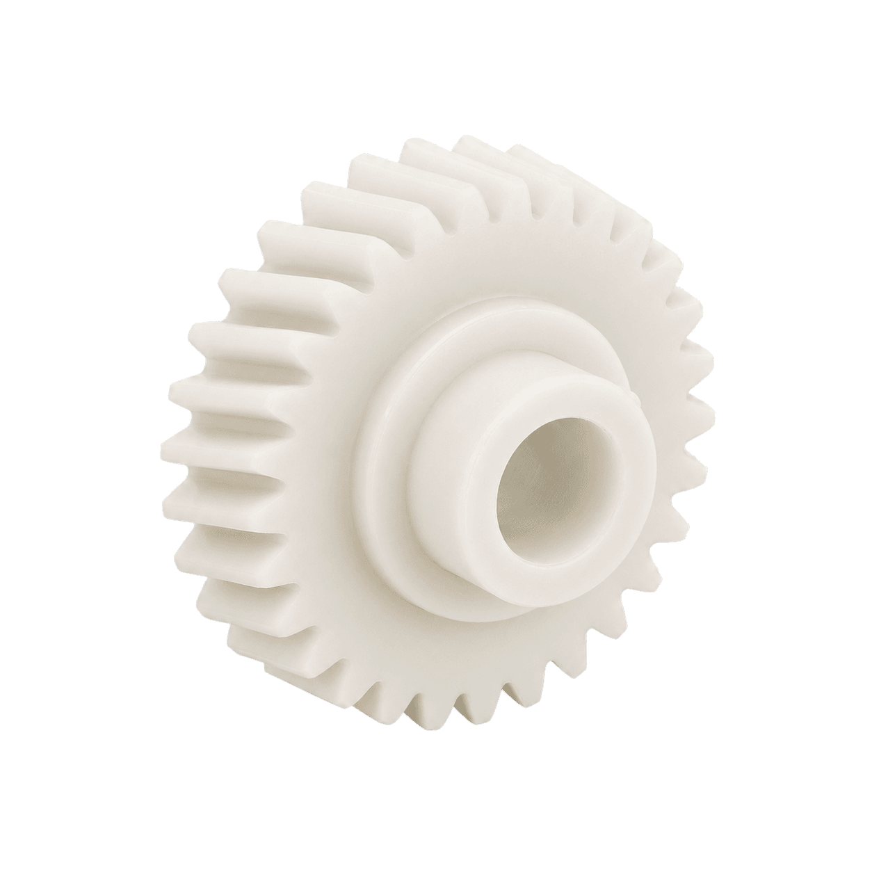
Representative application geometries only. Tooth form, hub design, mating material, support, and load path change the review inputs; the images do not identify a final resin grade.
- Compound spur gear
- Helical gear assembly
- Hubbed gear
Design Material Selection and Precision Molding Together
A gear that meets material calculations can still fail through poor roundness, concentricity, tooth spacing, profile, runout, bore fit, or backlash. Review gate position, flow direction, weld lines, wall transitions, rim and web thickness, hub and rib design, cooling balance, ejection, and cavity variation. These features affect molded shrinkage, residual stress, tooth accuracy, and the relationship between the bore and pitch circle.
TDS shrinkage is not a finished-gear tolerance. Establish the intended grade and molding window, then measure cavity-marked gears after a defined conditioning time. Check critical dimensions and functional mesh together. Machined prototypes can support early geometry or assembly work, but an injection-molded prototype is needed to reproduce molded skin, shrinkage, orientation, weld lines, and process variation.
Choose the Grade Direction From the Dominant Risk
An unfilled POM grade may be the first review direction where toughness, fatigue, precision molding, and a relatively balanced shrinkage response are important. Wear-resistant or low-friction modifications may be considered when contact life, operating force, noise, or dry-running behavior governs. Reinforced POM can change stiffness and creep response, but fiber orientation, tooth-surface behavior, weld lines, impact response, and counterpart wear must be assessed on the molded gear.
POM and PA should not be ranked generically. POM is often reviewed where low moisture response and dimensional consistency are important; a PA grade may offer a different balance of toughness, temperature behavior, wear, or shock response, while moisture conditioning can influence its dimensions and properties. Compare exact grades at the expected conditioned state and temperature using the same gear duty and acceptance criteria.
- Standard POM for the baseline balance of molding, fatigue and precision
- Wear-modified POM when tooth and counterpart wear govern service life
- Low-friction POM when running force, stick-slip, noise or heat governs
- Reinforced or alternative polymers only after orientation and trade-off review
Validate the Gear Train Under Representative Conditions
Use calculation and simulation to screen geometry and material candidates, but release the gear through testing. Mold traceable prototypes in the intended tool or a representative cavity and record material, lot, process, dimensions and conditioning. Test the complete gear train with the intended shafts, bearings, housing, mating gears, lubrication, alignment, load spectrum, speed, reversals, temperature and environment.
A useful test plan measures torque or efficiency, temperature near the mesh, noise or vibration, backlash, dimensional change, tooth-root damage, flank wear, mating-part wear, lubricant or debris condition, and failure cycles. Include startup, stall, shock, and endurance conditions where applicable. After the test, inspect the failure location and compare it with the original risk ranking before approving a grade or changing the design.
Separate acceptance criteria from failure observations
Passing a specified cycle requirement and documenting later wear are different records. In one customer-side POM gear-assembly test, the report recorded a pass against the project requirement alongside later observations of small-gear slipping and the functional condition of the second-stage gears.
For a comparable test, define load, motion, mating components, lubrication, environment, sample quantity, inspection items and failure criteria. Record the condition of each gear stage so that the findings can inform material and design reviews.