
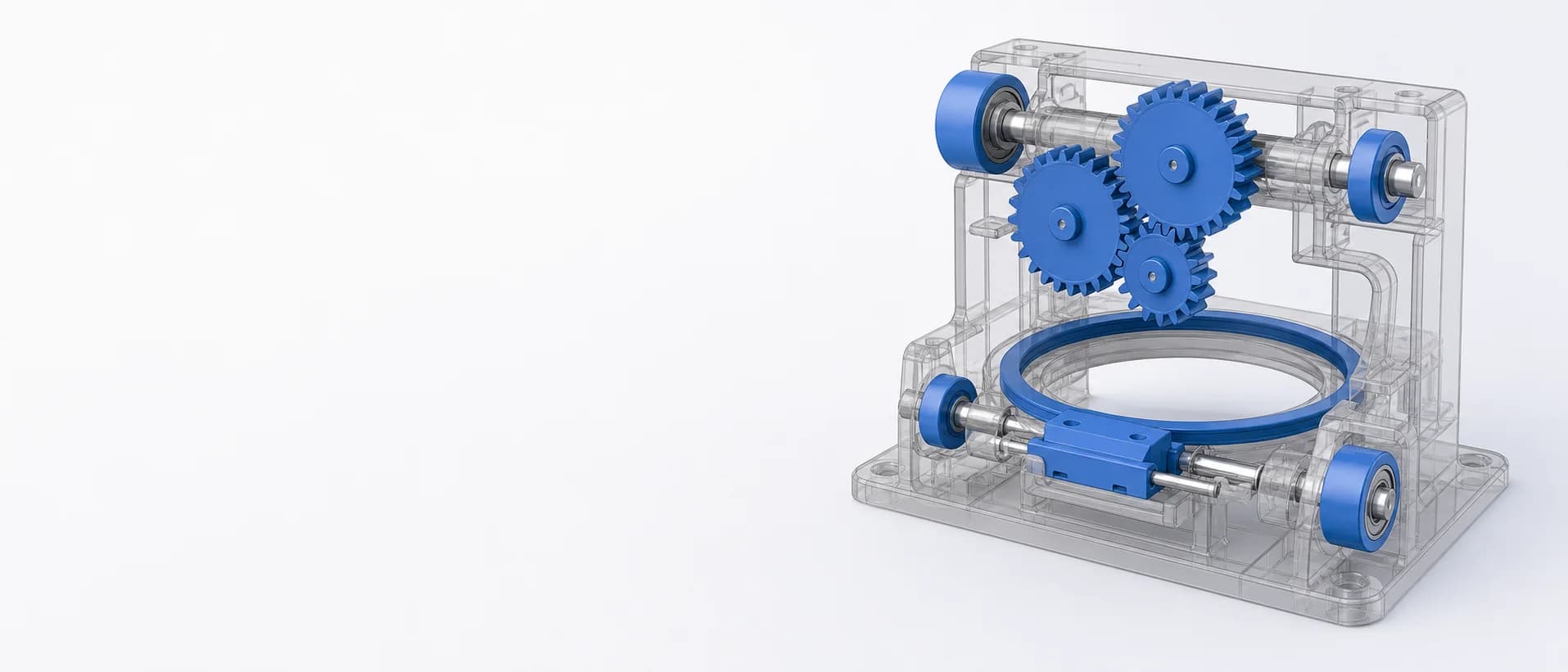
CAD visualization showing precision molded gears in an assembled transmission

Gear material solutions

Precision plastic gears

Compare POM materials for molded transmission gears, worm wheels and small gear mechanisms. Start with the load, wear or dimensional issue your part needs to solve.

Which POM direction fits your gear?

Use these three starting points to narrow the material family, then validate a grade in your assembly.

  • Balanced POM

    Best suited to
    For general transmission and dimensional consistency.
    Key validation
    Validate fatigue and dimensional stability at the actual torque, speed and temperature.
  • Wear-resistant POM

    Best suited to
    For sliding contact and friction or wear concerns.
    Key validation
    Test the actual mating part and lubrication. Friction data alone does not predict gear life.
  • Reinforced POM

    Best suited to
    For parts where stiffness and load deformation lead the review.
    Key validation
    Check fiber-related shrinkage and warpage, as well as wear on the mating part.
Selection checks and limitations

For spur, helical, pinion, planetary, internal, compound, worm-wheel, and sector gears.

Balanced / unfilled POM

A balanced POM option when stiffness, fatigue capability, dimensional control, moldability, and sliding behavior all matter.

It still requires validation at the actual torque, speed, temperature, lubrication condition, and target life.

Wear-resistant or low-friction POM

Relevant when dry running, flank wear, stick-slip, frictional heat, or noise has been confirmed as the limiting mechanism.

A generic friction result does not predict gearbox life; screen it with the actual mating gear and lubricant.

Reinforced POM

Relevant when tooth or hub deflection, creep, or structural stiffness is more limiting than surface wear.

Fiber orientation can change shrinkage, warpage, tooth-surface behavior, and counterface wear.

When POM may not fit

High temperature, humidity, chemical exposure, or a defined electrical requirement may move the project outside the practical POM window. In those cases, compare another polymer family instead of forcing POM into the application.

Open the material selection guide

Application case

ETM 100P for massage-chair armrest gears

A massage-chair customer used ETM 100P to address insufficient armrest gear wear resistance, then adopted the material for production and placed repeat orders. The customer-side validation recorded 1 sample at 20 kg per side, 25 ± 5°C and 45% RH: the assembly met the 27,500-cycle requirement, with small-gear wear and slipping recorded in further testing. The test result applies to that sample and those conditions.

Read the Case Study

Discuss your gear requirements

Share your current material, main concern and known operating conditions. We can help narrow the material options and identify what your assembly needs to validate.

Discuss Your Application
Full project information checklist

Part and mechanism

  • 2D drawing and, if available, 3D model
  • Gear type, tooth geometry, driver or driven position, shaft, bearing, and housing context
  • Current material, known grade, tooling stage, cavity count, and production volume

Operating and acceptance conditions

  • Torque, speed, duty, counterface, lubrication, temperature, humidity, and chemical exposure
  • Backlash, runout, dimensional tolerances, service life, noise, and current failure symptoms
  • Required TDS, SDS, COA, REACH, RoHS, or other grade-specific document paths

Expected output

A material shortlist, available grade data or document path, and a proposed molded-gear evaluation plan.

Production approval still depends on representative validation in the complete transmission.

Review material choices, molding priorities and reported project stages for similar parts.

View all customer cases

Working through a gear problem?

Open the topic that matches your current design or test question.

Wear, noise, distortion or premature failure

Wear or debris

Check first: Check actual torque and rpm, tooth temperature, contact pattern, alignment, counterface finish, and lubrication.

Material response: Screen wear-resistant or low-friction POM only when contact behavior remains the limiting factor.

Noise, heat, stick-slip, or binding

Check first: Check backlash, runout, center distance, shaft and housing alignment, hot and cold dimensions, and duty cycle.

Material response: Consider a friction-modified formulation only after geometry, assembly variation, and thermal clearance are separated from material behavior.

Root cracking or broken teeth

Check first: Check the crack origin, peak and stall loads, shock history, root geometry, gate and weld-line position, and molding defects.

Material response: Compare balanced or reinforced POM only after fatigue, stiffness, and overload have been identified as the governing constraint.

Bore, hub, or dimensional variation

Check first: Check interference, hub-web-rim balance, cooling, packing, gating, process history, and cavity-resolved measurements.

Material response: Correct tooling or process variation first; reinforcement can add anisotropic shrinkage and warpage risk.

Material selection criteria

Load and fatigue

  • Review continuous, peak, startup, stall, reversing, and shock loads together with tooth-root geometry.
  • Validate with production-intent geometry, duty cycle, temperature, and expected life.

Speed and frictional heat

  • Review rpm, continuous or intermittent duty, enclosure, cooling, and tooth temperature.
  • Track flank wear and temperature during a representative running test.

Contact system

  • Review mating material, hardness and finish, contact pattern, clearance, and lubrication.
  • Use the production counterface and lubricant when comparing wear behavior.

Accuracy, environment, and life

  • Review backlash, runout, tooth accuracy, temperature, humidity, fluids, service life, and noise together.
  • Confirm performance in the conditioned complete assembly, not from a loose gear alone.
Tooling and molding

Molded structure

  • Balance hub, web, rib, rim, and tooth sections to reduce uneven cooling and shrinkage.
  • Review bore, shaft, press-fit, spline, knurl, and insert stresses with the gear geometry.

Flow and dimensions

  • Review gate and weld-line position before tooling is frozen.
  • Set shrinkage compensation, packing, cooling, and inspection timing from the selected material and measured trial parts.
  • For reinforced compounds, evaluate fiber orientation and cavity-specific dimensional variation.
Validation on molded gears

Molded-part checks

  • Measure profile, pitch, runout, bore position, backlash, and cavity-to-cavity variation after the agreed conditioning period.
  • Inspect active flanks, tooth roots, gates, weld-line regions, flash, mismatch, and ejection damage.

Assembly checks

  • Run with the actual mating gear at representative torque, rpm, temperature, lubrication, and duty cycle.
  • Track wear, temperature, noise, backlash change, counterface condition, and failure location over the required period.